Showing posts with label Battery Charger. Show all posts

5v Powered Charge Pump Battery Charger

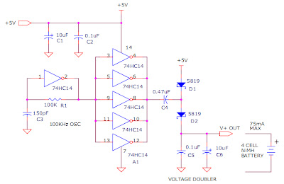
The circuit below will trickle charge a four cell pack of AA or AAA NiMH batteries.  The circuit draws current from the +5v available a USB connection and pumps about 70ma of current into the battery. This should be enough current to fully charge a pack of 2500ma-hour cells in about 36 hours.  The circuit uses a single 74HC14 hex Schmitt trigger inverter in conjunction with a voltage doubler charge pump circuit.


Circuit Projects: +5v Powered Charge Pump Battery Charger
Source: DiscoverCircuits

Making a Solar Energy Powered an iPhone Battery Charger

The project was termed as Mighty Minty Boost as it was developed to function as iPod/iPhone charger with solar power. Aside from being small, it has a large battery capacity of 3.7V at 2000mAh and it accepts input power from 3.7V to 7V. As shown in the images below, it can become a compact USB power supply when the solar cell is removed after charging. The Velcro is used to secure the Mighty Minty Boost inside a backpack or messenger bag after unplugging the solar cell.

For faster charging, a larger solar cell can be attached to the bag. Enough power can be generated to fully charge an iPhone in about 5.5 hours and an iPod Touch in 4 hours using a slightly larger solar cell with 6V at 250mAh. The charger will automatically switch to trickle charging when the cell reaches full charge. The charging current is limited to 100mA when charging using the mini USB port and the charging is limited to 280mA when charging using the barrel plug jack

Hacks and Mods: iPhone Charger Powered Thru Solar Energy
.
The materials needed to build the charger include a small solar cell, Lithium Polymer battery charger, minty boost kit, adhesive backed Velcro, Altoids tin, connector/wire, and small double adhesive squares as shown in the images below. An input power that ranges from 3.7V to 7V maximum can be accepted by the single cell Lithium Polymer. In bright sunlight, the solar cell maxes out at approximately 5V at 100mA. A larger solar cell with 6V at 250mA can be used for faster charging.

Hacks and Mods: iPhone Charger Powered Thru Solar Energy

The images below show the assembly of minty boost kit where a JST connector is soldered to the minty boost PCB instead of connecting the battery holder in the kit. The minty boost circuit is allowed to connect to the Lithium Polymer battery charger circuit with this tiny connector. The minty boost is tested by connecting the battery pack and the charger circuit, the Lithium Polymer battery connects to the connector marked GND on the charger board and the minty boost connects to the connector marked SYS.

Hacks and Mods: iPhone Charger Powered Thru Solar Energy

To fit the charger, a notch is cut out of the other side of the Altoids tin and used double sided adhesive to secure the charging circuit to the bottom of the Altoids as shown below. The bottom of either one of the circuit boards should not touch the bottom of the Altoids tin while reconnecting the minty boost PCB and the battery to the charging circuit.

Hacks and Mods: iPhone Charger Powered Thru Solar Energy

Connecting or adding the solar cell can be done in different ways. Shortening the connector leads and plugging the barrel plug into the barrel jack on the charging circuit is one way. The other method is using another JST connector to replace the connector and plugging it into the third connector marked 5V on the charging circuit. Since there is no bog barrel plug sticking out of the side of the tin, using the second method is cleaner.

As shown in the photos below, some 2” Velcro was used to attach the solar cell to the top of the Altoids. To help protect the battery, a layer of clear packing tape was used for wrapping. N top of the two circuit boards, the battery pack is then set down. A red LED on the charger board will light up when the Mighty Minty Boost is set out in the bright sun. The iPod/iPhone/USB powered device can be connected once it is fully charged.

Hacks and Mods: iPhone Charger Powered Thru Solar Energy

Balancing LiPo Cells

Things change fast in the electronics world, and that’s also true for recharge- able batteries. The rate of development of new types of rechargeable batteries has been accelerated by the steadily increasing miniaturisation of electronic equipment. LiPo cells have conquered the market in a relatively short time. Their price and availability have now reached a level that makes them attractive for use in DIY circuits.

Balancing LiPo Cells Circuit diagram

BalancingBalancing LiPo Cells Circuit diagram

Unlike its competitors Elektor Electronics has already published several articles about the advantages and disadvantages of LiPo batteries. One of the somewhat less well-known properties of this type of rechargeable battery is that the cells must be regularly ‘balanced’ if they are connected in series. This is because no two cells are exactly the same, and they may not all have the same temperature. For instance, consider a battery consisting of a block of three cells. In this case the outer cells will cool faster than the cell in the middle. Over the long term, the net result is that the cells will have different charge states. It is thus certainly possible for an individual cell to be excessively discharged even when the total voltage gives the impression that the battery is not fully discharged. That requires action – if only to prolong the useful life of the battery, since LiPo batteries are still not all that inexpensive. 

One way to ensure that all of the cells have approximately the same charge state is limit the voltage of each cell to 4.1 V during charging. Most chargers switch over to a constant voltage when the voltage across the batter terminals is 4.2 V per cell. If we instead ensure that the maximum voltage of each cell is 4.1 V, the charger can always operate in constant-current mode. 

When the voltage of a particular cell reaches 4.1 V, that cell can be discharged until its voltage is a bit less than 4.1 V. After a short while, all of the cells will have a voltage of 4.1 V, with each cell thus having approximately the same amount of charge. That means that the battery pack has been rebalanced. 

The circuit (Figure 1) uses an IC that is actually designed for monitoring the supply voltage of a microcontroller circuit. The IC (IC1) normally ensures that the microcontroller receives an active-high reset signal whenever the supply voltage drops below 4.1 V. By contrast, the out-put goes low when the voltage is 4.1 V or higher. In this circuit the output is used to discharge a LiPo cell as soon as the voltage rises above 4.1 V. 

When that happens, the push-pull output of IC1 goes low, which in turn causes transistor T1 to con-duct. A current of approximately 1 A then flows via resistor R1. LED D2 will also shine as a sign that the cell has reached a voltage of 4.1 V. The function of IC2 requires a bit of explanation. The circuit built around the four NAND gates extends the ‘low’ interval of the signal generated by IC1. That acts as a sort of hysteresis, in order to prevent IC1 from immediately switching off again when the voltage drops due the internal resistance of the cell and the resistance of the wiring between the cell and the circuit. The circuitry around IC2 extends the duration of the discharge pulse to at least 1 s.
Balancing w3


Figure 2 shows how several circuits of this type can be connected to a LiPo battery. Such batteries usually have a connector for a balancing device. If a suit-able connector is not available, you will have to open the battery pack and make your own connections for it. The figure also clearly shows that a separate circuit is necessary for each cell.

LM317 to create constant current of 2mA?

I have a circuit where I want to have a constant current of 2mA through a variable resistor. I've been told that I could probably use a LM317 as a current regulator, with one resistor on the ouput. But I've read some places that the LM317 takes minimum 5-10mA load to function correctly.

How can I achieve a constant current output of 2mA when I don't know the resistance of the variable resistor?

The input voltage is about 2.755V. Output voltage doesn't matter, just the current.


Here's an image to my feeble attempt at a schematic:


enter image description here


The LM317 with the single series resistor between output and adjust input is actually a fixed current source, not a current limiter. You don't need the LM317 to create a current limiter, a few discrete components will do:
enter image description here
For a limiting at 2mA you select a 330Ω resistor for RSENSE. If there flows 2mA through it Q2 will start to conduct and reduce the base voltage of Q1, so that its current is cut off.
edit (re changed question)

Maybe you're focusing too much on the LM317. If you need a constant current you could use the LM234 which is a programmable current source for up to 10mA. You set the current with a resistor.

Particularly LM317 Circuit With 12v Battery Charger Circuit

Introduction
The LM317 is AN adjustable three terminal transformer that is capable of supply 1.2 to 37 volts with a secure 1.5A output current. The LM317 is prepackaged terribly} normal electronic transistor package that makes it very simple to mount in your circuits. 
Schematic


Overview
The LM317 series of adjustable 3-terminal positive voltage regulators is capable of supply in more than 1.5A over a 1.2V to 37V output vary. they're exceptionally simple to use and need solely 2 external resistors to line the output voltage. Further, each line and cargo regulation square measure higher than normal mounted regulators.

In addition to higher performance than mounted regulators, the LM317 series offers full overload protection out there solely in IC's. enclosed on the chip square measure current limit, thermal overload protection and safe space protection.

The LM317 makes AN particularly easy adjustable change regulator, a programmable output regulator, or by connecting a set electrical device between the adjustment pin and output, the LM317 may be used as a preciseness current regulator. provides with electronic conclusion may be achieved by clamping the adjustment terminal to ground that programs the output to one.2V wherever most masses draw very little current.

Pinout

Options


Specifications

  • Guaranteed 1% output voltage tolerance (LM317A)
  • Guaranteed max. 0.01%/V line regulation (LM317A)
  • Guaranteed max. 0.3% load regulation (LM117)
  • Guaranteed 1.5A output current
  • Adjustable output down to 1.2V
  • Current limit constant with temperature
  • P + Product Enhancement tested
  • 80 dB ripple rejection
  • Output is short-circuit protected
Output Formula

Circuit
Once you have learnt enough you can now put the LM317 into use and make the following circuit:
  
12v Battery Charger Circuit
The circuit may be accustomed charge 12V lead acid batteries.

Overview

Pin one of the LM317 IC is that the management pin that is employed to manage the charging voltage, Pin a pair of is that the output at that the charging voltage seems, Pin three is that the input to that the regulated DC offer is given.

The charging voltage and current is controlled by the electronic transistor (Q1), electrical device (R1) and POT (VR1). once the battery is 1st connected to the charging terminals, the present through R1 will increase. This successively will increase the present and voltage from LM317. once the battery is totally charged the charger reduces the charging current and also the battery are charged within the trickle charging mode.

Circuit


Notes
  • The input voltage to the circuit should be a minimum of 3V more than the expected output voltage. luminous flux unit 317 dissipates around 3V throughout its operation. Here I used 18V DC because the input.
  • The charging voltage may be set by victimization the POT (VR1).
  • The luminous flux unit 317 should be mounted on a sink.
  • All capacitors should be rated a minimum of 25V.
  • You'll be able to use crocodilian clips for connecting the battery to the charger.

Battery Equality Monitor

Almost all 24V power systems in trucks, 4WDs, RVs, boats, etc, employ two series-connected 12V lead-acid batteries. The charging system can only maintain the sum of the individual battery voltages. If one battery is failing, this circuit will light a LED. Hence impending battery problems can be forecast. The circuit works by detecting a voltage difference between the two series connected 12V batteries. Idle current is low enough to allow the unit to be permanently left across the batteries.
 .

Battery Equality Monitor Circuit diagram:

.

battery_equality_monitor_schematic_circuit_diagramw
Battery Equality Monitor Circuit Diagram

Parts:
R1 = 2.K
R2 = 4.7K
R3 = 39K
R4 = 39K
R5 = 1.5K
R6 = 1.5K
Q1 = BC547
Q2 = BC547
Q3 = BC557
D1 = 3mm Red LED
D2 = 3mm GreenLED
B1 = DC 12 Volt
B2 = DC 12 Volt

Make Your Iphone Battery Last Longer

I’ve owned a Iphone for a while now, it’s an amazing phone, the best I have ever used so far. But when I first started using it, my only concern was that the battery didn’t last as much as I expected. After two days, it was gone, and when I needed it, the phone just didn’t turn ON. I used to let the wireless on almost all the time and downloading many new apps. Now that I have some more experience on how my little gadget works, I will try to share some ideas on how you can optimize your iphone’s battery life and have a better iExperience.

iphone


  • Wireless connectivity will drawn your battery even if you are not using it. Keeping it on, it will always try to connect to some open hot spot, try to check your emails and much more. So a good idea is to turn it on when using, and after, turn it off.
  • Bluetooth have a similar battery usage as Wi-Fi, so there’s not much reason to leave it on if you are not using it (I believe that the most common usage for bluetooth today is the headsets and car kits).
  • Auto-Brightness is a interesting thing apple made to make the battery last longer. It uses iphone’s camera to adjust brightness based on the lighting conditions outside, so it will automatically set, for example, to make it less bright when you are on a dark place. Great feature!
  • Music EQ will have a significant battery usage if you listen to your songs for many hours everyday, as it uses more processing power. So if you want to charge less your iphone, it is another thing you may consider turning it off.
  • Heat can be a problem to your iphone, as it is a very bad thing to lithium-ion batteries, making them harder to charge and destroying it due the intense ionization. So remember to never let your phone in a hot place such as inside a car or in direct sunlight. If you are using some kind of carrying case, you need to be even more careful about this, and remember to take it off when charging your mobile, as it gets warm when charging.
  • Keep it charging! After putting your phone to charge, leave it there for some hours more after it says it’s full. It will make your phone battery last much more, you will be surprised! After done that, my iphone battery lasted more then a week, way more if you compare to the 2-3 days when I was disconnecting if from the dock just after it says its full.
  • Background Programs! This is important, new iphones, such as Iphone4 allows you to run multiple apps on the background, but this will drain your battery fast if you forget to close them. To do this, double click on the round button and it will show all the apps currently running, keep clicking in one of the apps and a red “X” will apear, then you can close all apps.
  • What else do you do to make your iphone battery last longer?


    Source by : link

    Simple Solar charger circuit project using transistors

    Solar charger circuit project using transistors. A very simple solar charger circuit project can be designed using few external electronic parts . This simple solar charger circuit is capable of handling charge currents of up to 1A. Alternate component values are given in the figure for lower current applications.


    Solar charger circuit project using transistors


    12V-SLA-chargher Solar charger circuit project using transistors circuit diagram

    The only adjustment is the voltage trip point when the current is shunted through the transistor and load resistor. This should be set with a fully charged battery. As the transistor and R3 have the entire panel’s output across them when the battery is fully charged, all of the current from the panel will be going through R3 and the Darlington transistor TIP112, so these must be well heat sunk. Adjust R1 for the trip point, usually 14.4 V – 15 V for a 12 V SLA or a 12 V Ni-Cd battery.


    source : Link

    Simple Lead Acid Battery Charger #2

    The above pictured schematic diagram is just a standard constant current model with a added current limiter, consisting of Q1, R1, and R4. The moment too much current is flowing biases Q1 and drops the output voltage. The output voltage is: 1.2 x (P1+R2+R3)/R3 volt. Current limiting kicks in when the current is about 0.6/R1 amp. For a 6-volt battery which requires fast-charging, the charge voltage is 3 x 2.45 = 7.35 V. (3 cells at 2.45v per cell). So the total value for R2 + P1 is then about 585 ohm. For a 12 V battery the value for R2 + P1 is then about 1290 ohm. 

    For this power supply to work efficiently, the input voltage has to be a minimum of 3V higher than the output voltage. P1 is a standard trimmer potentiometer of sufficient watt for your application. The LM317 must be cooled on a sufficient (large) coolrib. Q1 (BC140) can be replaced with a NTE128 or the older ECG128 (same company). Except as a charger, this circuit can also be used as a regular power supply.

    Lead Acid Battery Charger circuit diagramBattery ChargerBattery ChargerParts List:

    R1 = 0.56 Ohm, 5W, WW
    R2 = 470 Ohm C2 = 220nF
    R3 = 120 Ohm
    R4 = 100 Ohm
    C1 = 1000uF/63V
    Q1 = BC140
    Q2 = LM317, Adj. Volt Reg.
    C3 = 220nF (On large coolrib!)
    P1 = 220 Ohm

    Battery Charger LM317

    Lead Acid Battery Charger circuit is highly recommended to recharge battery. And recommended that maximum voltage 24V 7A battery, so you can recharge a battery simultaneously. Battery Charger has been little use of several components such as diodes, electrolytic capacitors, transistors, resistors, and also for strengthening of the voltage and current stresses. And also do not forget to lowering electric voltage 220V to 20V-35V 5-10 Ampere suitable for Lead Acid Battery Charger circuit.


     List of components for the circuit Lead Acid battery:

    R1               = 1Ω 2w
    R2               = 100Ω
    R3               = 220Ω
    R4               = 10KΩ Trim
    D1 - D5       = IN4004
    Q1               = BC547
    IC 1             = LM317
    C1 - C2       = 1000µF 50V
    C3               = 470µF 50V

    Transformer I mentioned above can use the 5A - 10A with a secondary voltage of about 20Volt-35Volt AC. My advice to IC please be cooler, because when the circuit and well even IC LM317 works it causes IC hot. Also to assemble the components using PCB (Printed works Circuit Board) qualified with a good track, as well as the components that will be used not forget to check back whether good or not, so it will also produce good results.

    Simple Lead Acid Battery Charger 1

    Except for use as a normal Battery Charger, this circuit is perfect to 'constant-charge' a 12-Volt Lead-Acid Battery, like the one in your flight box, and keep it in optimum charged condition. This circuit is not recommended for GEL-TYPE batteries since it draws to much current. The above circuit is a precision voltage source, and contains a temperature sensor with a negative temperature coλficient. Meaning, whenever the surrounding or battery temperature increases the voltage will automatically decrease. Temperature coλficient for this circuit is -8mV per °Celcius. A normal transistor (Q1) is used as a temperature sensor. This Battery Charger is centered around the LM350 integrated, 3-amp, adjustable stabilizer IC. Output voltage can be adjusted with P1 between 13.5 and 14.5 volt.

    T2 was added to prevent battery discharge via R1 if no power present. P1 can adjust the output voltage between 13.5 and 14.5 volts. R4's value can be adjusted to accommodate a bit larger or smaller window. D1 is a large power-diode, 100V PRV @ 3 amp. Bigger is best but I don't recommend going smaller. The LM350's 'adjust' pin will try to keep the voltage drop between its pin and the output pin at a constant value of 1.25V. So there is a constant current flow through R1. Q1 act here as a temperature sensor with the help of components P1/R3/R4 who more or less control the base of Q1. Since the emitter/base connection of Q1, just like any other semiconductor, contains a temperature coλficient of -2mV/°C, the output voltage will also show a negative temperature coλficient.

    Battery Charger 1 That one is only a factor of 4 larger, because of the variation of the emitter/basis of Q1 multiplied by the division factor of P1/R3/R4. Which results in approximately -8mV/°C. To prevent that sensor Q1 is warmed up by its own current draw, I recommend adding a cooling rib of sorts. (If you wish to compensate for the battery-temperature itself, then Q1 should be mounted as close on the battery as possible) The red led (D2) indicates the presence of input power.Depending on what type of transistor you use for Q1, the pads on the circuit board may not fit exactly (in case of the BD140).

    How Build a Solar Charger use IC LM317

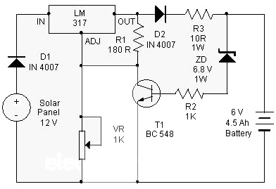
     At this point is a Solar Charger Circuit to is used to charge information Acid otherwise Ni-album batteries using the solar energy power. The circuit harvests solar energy to charge a 6 volt 4.5 Ah rechargeable battery in favor of various applications. The stallion has Voltage and Current supervision and terminated voltage restrict sour facilities.

    Circuit uses a 12 volt solar panel and a changeable voltage supervisor IC LM 317. The solar panel consists of solar cells each one rated on 1.2 volts. 12 volt DC is presented from the panel to charge the battery. Charging current passes through D1 to the voltage watchdog IC LM 317. By adjusting its Adjust pin, output voltage and current can subsist regulated.

    How Build a Solar Charger use IC LM317
    VR is placed amid the adjust pin and ground to provide an output voltage of 9 volts to the battery. Resistor R3 confine the charging current and diode D2 prevents discharge of current from the battery. Transistor T1 and Zener diode ZD conduct yourself having the status of a stop rotten switch at what time the battery is ample. Normally T1 is rancid and battery gets charging current.
    After the terminal voltage of the battery rises over 6.8 volts, Zener conducts and provides station current to T1. It followed by turns on education the output of LM 317 to prevent charging. If you want to specific voltage / current output , you can replacing ZD on the circuit above.

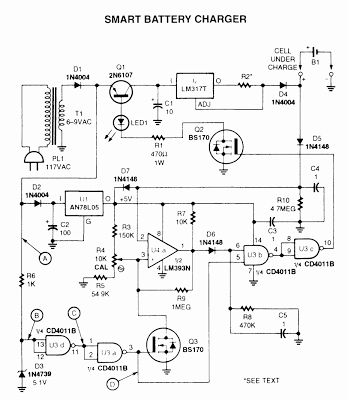
    Build a Smart battery charger

    This is a smart battery charger can protect your vehicle's battery from failing and will prolong its life – they're fully automatic so you can connect and forget.

    http://diagramdigital.blogspot.com/2012/12/build-smart-battery-charger.html

    Simple Car Battery Voltage Monitor Circuit

    This circuit is used to monitor the battery voltage to display a dual-colored LED status of the battery to. If the LED “green”battery voltage exceeds 11.9 volts. If the yellow LED, battery voltage 11.9 to 11.5 volts. If the LED is “red” If the battery voltage below 11.5 volts. You can of course change the trigger points by the trimmer resistors and / or changing the value of the resistors in the divider.
     .
     Simple Car Battery Voltage Monitor Circuit Diagram

    .
    Simple Car Battery Voltage Monitor Circuit diagram

    A dual op amp is used as a comparator. The green LED on the board, until the voltage exceeds 11.5 volts. The red LED illuminates when the voltage falls below 11.9 volts to the circuit. Therefore, in the 11.9 to 11.5 volts, both LEDs are on, producing a slightly yellow color. When the voltage falls below 11.5 V, the green LED, and now only the red LED flashes to indicate low voltage.

    Parts List
    R1=1K2
    R2-3-4=680R
    R5=15K
    R6=10K
    R7-8-9-10=1K
    IC1=LM324
    D1=5V6 /0.5W Zener
    D2-3-4-5=LED
    RV1=10K trimmer

     Is recommended that multi-shaper for V1 and V2. Muti-trimmer makes it much easier to trigger points to make as a less expensive single-turn trimmer. The trimmer can be completely eliminated if you have access to a range of 1% resistors and has had calculated carefully. You would also want to provide more accurate reference voltage as the common 78L05 regulator.


    Lead Acid Battery Protector

    The circuit described here can be used to  ensure  that  a  12 V  sealed  lead  acid  (SLA)  gel battery isn’t discharged too deeply. The  principal part of the circuit is a bistable relay,  which is driven by the output of an op amp. 

    Lead Acid Battery Protector Circuit diagram :

    Lead Acid Battery Protector dd
    Lead Acid Battery Protector Circuit Diagram
    The battery voltage is first reduced via D1, R1,  P1 and R2, and then continuously compared  with a reference voltage set up by diode D2.  When the battery discharges too much and  its terminal voltage drops below the level  set by P1, the output of the opamp becomes  High, which causes the relay to toggle. This  in turn isolates the load from the battery. The  battery can be reconnected via S1 once the  battery has been replaced or recharged. 

    The relay used in the prototype is a 5 V bistable type made by Omron (G6AK-234P-ST-US  5 VDC). The two windings of the relay each  have a resistance of 139 Ω (for the RAL-D 5  W-K made by Fujitsu this is 167 Ω). When the  battery voltage starts to become too low and  the relay is being reset the current consumption of the circuit is about 45 mA. Shortly  after the load has been disconnected, when the battery voltage rises above the reference  voltage again, the reset coil will no longer be  powered and the current consumption drops  back to about 2.5 mA. 

    The range of P1 has intentionally been kept  small. With a reference voltage of 5.6 V (D2)  and a voltage drop of 0.64 V across D1, the circuit reacts within a voltage span of 11.5 V and  11.8 V. This range is obviously dependent on the zener diode used and the tolerance. 

    For a greater span you can use a larger value  for P1 without any problems. With the potentiometer at its mid setting the circuit switches  at about 11.6 V.

    Voltage Tester for Model Batteries

    With a suitable load, the terminal voltage of a NiCd or lithium-ion battery is proportional to the amount of stored energy. This relationship, which is linear over a wide range, can be used to build a simple battery capacity meter. 

    Voltage Tester for Model Batteries Circuit Image :
     Voltage Tester for Model Batteries Image
    Voltage Tester for Model Batteries Circuit Image 

    This model battery tester has two functions: it provides a load for the battery, and at the same time it measures the terminal voltage. In addition, both functions can be switched on or off via a model remote-control receiver, to avoid draining the battery when it is not necessary to make a measurement. The load network, which consists of a BC517 Darlington transistor (T2) and load resistor R11 (15 Ω /5 W), is readily evident. When the load is active, the base of T1 lies practically at ground level. Consequently, T1 conducts and allows one of the LEDs to be illuminated. 

    Circuit Diagram :
    Voltage Tester for Model Batteries-Circuit Diagram

    The thoroughly familiar voltmeter circuit, which is based on the LM3914 LED driver, determines which LED is lit. The values of R6 and R7 depend on the type and number of cells in the battery. The objective here is not to measure the entire voltage range from 0 V, but rather to display the portion of the range between the fully charged voltage and the fully discharged voltage. Since a total of ten LEDs are used, the display is very precise. For a NiCd battery with four cells, the scale runs from 4.8 V to 5.5 V when R6 = R7 = 2 kΩ. The measurement scale for a lithium-ion battery with two cells ranges from 7.2 V to 8.0 V if R6 = 2 kΩ and R7 = 1 kΩ. 

    For remote-control operation, both jumpers should be placed in the upper position (between pin 1 and the middle pin). In this configuration, either a positive or negative signal edge will start the measurement process. A positive edge triggers IC1a, whose output goes High and triggers IC1b. A negative edge has no effect on IC1a, but it triggers IC1b directly. In any case, the load will be activated for the duration of the pulse from monostable IC1b. Use P12 to set the pulse width of IC1a to an adequate value, taking care that it is shorter than the pulse width of IC1b. 

    If the voltage tester is fitted into a remote-controlled model, you can replace the jumpers with simple wire bridges. However, if you want to use it for other purposes, such as measuring the amount of charge left in a video camera battery, it is recommended to connect double-throw push-button switches in place of JP1 and JP2. The normally closed contact corresponds to the upper jumper position,while the normally open contact corresponds to the lower position.

    Parts :
    Resistors:
    R1,R2 = 47kΩ
    R3 = 100kΩ
    R4 = 500kΩ
    R5 = 1kΩ
    R6,R7 = see text (1% resistors!)
    R8 = 1kΩ5
    R9 = 1kΩ2
    R10 = 330Ω
    R11 = 15Ω 5W
    R12 = 15kΩ
    P1 = 100kΩ preset
    Capacitors:
    C1 = 10nF
    C2 = 100nF
    Semiconductors:
    D1-D10 = LED, red, high effi-ciency
    T1 = BC557
    T2 = BC517
    IC1 = 74HC123
    IC2 = LM3914AN
    Miscellaneous:
    PC1,PC2,PC3 = solder pin
    JP1,JP2 = jumper or pushbutton

    PCB Layout :
    B. PCB Laout
    Voltage Tester for Model Batteries PCB Layout


    Copyright : Elektor

    High Voltage Generator Circuit Diagram

    This high voltage generator was designed  with the aim of testing the electrical break-down protection used on the railways. These  protection measures are used to ensure that  any external metal parts will never be at a  high voltage. If that were about to happen,  a very large current would flow (in the order  of kilo-amps), which causes the protection  to operate, creating a short circuit to ground effectively earthing the metal parts. This hap-pens when, for example, a lightning strike hits  the overhead line (or their supports) on the  railways. 

    This generator generates a high voltage of  1,000 V, but with an output current that is limited to few milliamps. This permits the electrical breakdown protection to be tested with-out it going into a short circuit state. The circuit uses common parts throughout: a  TL494 pulse-width modulator, several FETs or  bipolar switching transistors, a simple 1.4 VA  mains transformer and a discrete voltage multiplier. P1 is used to set the maximum current  and P2 sets the output voltage. 

    High Voltage Generator Circuit diagram :
    High Voltage Generator-Circuit Diagram
    High Voltage Generator Circuit Diagram

    The use of a voltage multiplier has the advantage that the working voltage of the smoothing capacitors can be lower, which makes them easier to obtain. The TL494 was chosen  because it can still operate at a voltage of  about 7 V, which means it can keep on working even when the batteries are nearly empty.  The power is provided by six C-type batteries, which keeps the total weight at a reason-able level. 

    The 2x4 V secondary of AC power transformer  (Tr1) is used back to front. It does mean that  the 4 V winding has double the rated voltage  across it, but that is acceptable because the  frequency is a lot higher (several kilo-Hertz)  than the 50 Hz (60 Hz) the transformer is  designed for. The final version also includes a display of the  output voltage so that the breakdown volt-age can be read. 

    From a historical perspective there follows a  bit of background information. In the past a different system was worked  out. Every high-voltage support post has a  protection system, and it isn’t clear when  the protection had operated and went into  a short-circuit state due to a large current  discharge. 

    Since very large currents were involved, a certain Mr. Van Ark figured out a solution for this.  He used a glass tube filled with a liquid containing a red pigment and a metal ball. When  a large current discharge occurred the metal  ball shot up due to the strong magnetic field,  which caused the pigment to mix with the liquid. This could be seen for a good 24 hours after the event. After a thunder storm it was  easy to see where a discharge current took  place: one only had to walk past the tubes  and have a good look at them. 

    Unfortunately, things didn’t work out as  expected. Since it often took a very long  time before a discharge occurred, the pigment settled down too much. When a dis-charge finally did occur the pigment no  longer mixed with the liquid and nothing was  visible. This system was therefore sidelined,  but it found its place in the (railway) history  books as the ‘balls of Van Ark’.


    Author : By Jac Hettema

    Solar Charger Circuit Diagram

    Simple Solar charger circuit to take advantage of sunlight shining on the earth can continue to be utilized to serve as a power source so that we can at least save on electricity prices continuing to rise, below is one of a series of simple power plant can be created and used to fill your motorcycle battery or for emergency lights.

    The circuit scheme of Solar Power Generation
    Simple Solar charger circuit
    Sunlight is received by the solar panels are then processed into electricity, but electricity generated from each panel is still too small where the 8 Cell Panel arranged in series only mrnghasilkan voltage of approximately 4 volts with a current 200 mA.
    nah therefore required an electronic circuit to increase the voltage and current enough to be used as a Battery Charger.
    Electronic Rainmaking act as a series of DC to DC Inverter (DC to DC Inverter), which was built by two pieces of Capacitor, Resistor 1, a transistor, a diode, and a coil which is the point of the creation of this series.

    The circuit was built with a single oscillator system (blocking oscillator) which was built by the transistor and a coil in which the primary winding totaling 45 turns and 15 turns in the secondary as feedback to provide the voltage at the base of the transistor output of the primary winding connected to the diode and used to The battery charging.

    When the circuit is coupled with the Emergency Neon Lights will certainly get enough voltage to light at night for free. because its batteries during the day in charge by the sun.

    The success of this experiment is a way of making a coil which is the same way with the topic of emergency fluorescent lights
    .
    List of Components
    • 8 cell 0.5v 200 mA solar panel (sold in many electronics stores) or make use of solar panels used a calculator that is damaged / not used anymore you dismantle it and take solarcell
    • Capacitor 100 UF
    • Capacitor 10 UF
    • Transistor TIP 31 or similar
    • Resistor 1 K
    • Diode BY 207 (Diada 5 Ampere) or similar
    • Accu Motor.
    • Approximately 3 meters of 0.25 mm diameter wire email.>
    • Ferite rods are frequently used in radio-AM radio.

    Automatic 9-volt Battery Charger

    Good care given to your NiCad batteries will ensure a long life. However, they do need to be handled and charged with special care.
    It is therefore important to first discharge the NiCad to 1 Volt per cell, ensure that the battery is discharged, and then start the charge cycle.

    recommend a charge current of 1/10th the capacity for a duration of about 15 hours uninterrupted.
    In reality, we learn some hard lessons when we forget to switch the charger off after the 15 hours and find that one or more cells inside the battery no longer
    accept a charge. That is the very reason that the circuit above is fully automated.
    The only thing to do is connect the battery and press the 'Start' button. When the discharge cycle is finished the circuit switches over to charge for 15 hours. After
    the 15 hours the circuits maintains a trickle charge to keep the battery 'topped-up


    Before I go into the schematic details I like to explain some of the component descriptions in the schematic. Jan Hamer lives in the Netherlands and so the circuit
    details are based on european standards.
    120E, 150E, etc. The 'E' just stands for Ohms so 120 ohm, 150 ohm. The original circuit specified the HEF type of cmos IC's which are not readily available in
    most of Canada. So just get any other type of CMOS chip like the MC4011, MC4020, MC4047 from Motorola. Any other type will do fine too. The BC548B is
    replaceble by a NTE123AP (NOTE: make sure it is the 'AP' type, the regular NTE123A is a total different transistor), ECG123AP, and the 2N3904 will work
    also. Watch for the correct pin locations since the BCE may be reversed with this european type. The LM317T is a TO-220 type and replaceble with a ECG956
    or NTE956. The LM339N can be replaced with a ECG834 or NTE834
    Although this circuit looks quite impressive and maybe a bit difficult it is certainly not difficult to understand. The circuit needs to be hooked-up to a DC supply
    voltage of between 16.5 and max 17.5 volt, otherwise the CMOS IC's will go defective. Because I didn't feel like to design a seperate powersupply for this circuit
    I connected it to my fully adjustable bench top powersupply.
    First we connect a 'to-be-charged' 9-volt nicad battery to the appropriate connections. Then hook it up to the powersupply. Upon connection the 1nF capacitor
    starts up the two RS Flip-Flops formed by IC1a, IC1b, IC1c, IC1d, and pulls pins 3 and 10 'high' and pins 4 and 11 'low'. The clock pulses are created by the free-
    running multivibrator IC4. IC4's frequency is determined by the 10uF capacitors, the 220K resistor and the 100K trimpot. The clock runs continuesly but the
    counter behind, IC5, is not counting yet because pin 11 (the master-reset) is kept high. When the 'START' button is pressed, output pin 4 from IC1a goes high
    and biases TR4, which is made visible by the Red LED (D9) which remains lit. The NiCad is now being discharged via this transistor and the 100 ohm resistor.
    The 10K trimpot (at the right of the diagram) is adjusted in such a way that when the battery voltage dips below 7 volt, the output of IC3 goes LOW and the
    output pin 11 of IC1a HIGH. At hte same time the output pin 10 of IC1d goes LOW, and the red LED turns off.
    Because output pin 11 went HIGH the green LED (D8) lights up and at the same time the voltage level rises causing the battery to be charged. The charge-
    current is determined by the 120 ohm, 150 ohm, and the trimpot of 1K, at the right side of IC2. Actually we could have used one resistor, but the output voltage
    of different brands for IC2 may differ, by about 1.25 volt.
    Because the charging current is devided by value of the resistors, with the trimpot the current can be adjusted to the correct value of your own 9-volt NiCad. (In
    my case, the battery is a 140 mA type, so the charge current should be adjusted for 14 mA (c/0.1).
    At the same time the LOW of output pin 10 from IC1d starts the counter of the clock. On pin 9 of IC5 appear pulses which light up the red LED. This is
    implemented for two reasons, the clock-frequency can, with the 100K trimpot, be adjusted to the correct value; the red LED has to come ON for 6.59 seconds
    and for the same duration going OFF and except for that fact the green LED, who indicates the charge current, can be checked if the total charge-time is correct.
    When the counter has reached 8192 pulses ( x 6.59 = 53985.28 sec = 14.99 hours) the output pin 3 of IC5 goes high again, transistor Tr1 activates and resets the
    two flip-flops to the start position.

    The charging process stops and goes over to trickle charge via the 10K resistor and the D2 diode and keeps the battery topped-up.
    The adjustments of the project are really very simple and nothing to worry about. Turn the walker of the 10K pot in the direction of the 12K resistor, ground
    connection point of 10K resistor/diode D2, like the adjustment pin of IC2, apply a voltage of 7-volt to the battery connection terminals, switch the power ON and
    slowly turn the pot backward until the greeen LED starts to light up. Switch OFF the power and take away the connections you made to make the adjustment.
    Insert an amp-meter between the battery and the output connection and again switch the power ON. The battery will, in case it is not completely empty, totally
    discharged (to a safe level) and as soon as the 7 volt margin is reached goes over to the charge cycle. The charge current is at this time adjusted via the 1K
    trimpot (which is connected in series with the 150 Ohm resistor and in parallel with the 120 ohm resistor) accurately to the desired value.
    Addendum: It is strongly recommended to include small 100nF ceramic capacitors over the powersupply lines feeding EACH CMOS IC to keep possible
    interference to a negliable value.
    Jan Hamer 

    Copyright © 1995 - 2001 Tony van Roon
    Build a Motorcycle Headlamp Battery Over Discharge Protector Circuit Diagram

    A simple motorcycle battery over discharge protector circuit is explained in the following post. The circuit will prevent the battery from over discharging by the motorcycle headlamp whenever the mo-bike alternator is not enabled or is idling in the neutral mode in which case the battery is normally subjected to excess loads via the headlamp bulb.

    Motorcycle batteries are normally a lot smaller with their sizes and ratings compared to the vehicle and the usage. The main use of the battery present in mo-bikes is for enabling electronic start through a press of the given start button.

    However this small sized battery also has to undergo further stresses while operating excess loads such as the horn, the indicator lights, the tail light and the brake light.

    Even though the above loads mostly tend to depend on the motorcycles battery power, these do not affect the battery charge level significantly.

    The one that truly affects the battery is the motorcycle headlamp, which when switched ON starts drawing huge current via the alternator and the battery in a shared manner. This the reason why we normally see the headlight intensity vary with varying mo-bike speeds.

    At higher speeds the alternator shares the load to fair extents, but in cases when the vehicle is not moving or is idling in the neutral mode, the lamp starts consuming substantial amount of battery power, depleting it's charge to dangerous lower levels, and this may happen within minutes if not switched OFF.

    The proposed circuit of motorcycle headlamp battery discharge protector circuit is intended exactly to tackle this issue automatically.

    It's nothing complicated, it's a simple low battery cut-off circuit set to switch of the link between the battery and the headlamp whenever the battery level falls below some set predetermined level.

    The circuit may be understood as follows:

    The opamp 741 IC is configured as a comparator here.

    It's pin#3 is referenced at a fix voltage determined by the connected zener voltage. Pin#2 of the IC executes the function of the sensing input and keeps the output of the opamp pin#6 low as long as its potential stays above the reference value of pin#3.

    The above condition is held in position as long as the battery voltage is above the set safe threshold level, which in turn keeps the output pin#6 at a low logic level.

    The low at pin#6 ensures that the p-mosfet is allowed to conduct and illuminate the attached headlamp.

    Therefore the headlamp is allowed to receive the required power through the mosfet as long as battery voltage continues to be above the safe threshold.

    Now suppose the battery level begins falling beow the set level, this would mean pin#2 potential going down below the reference level at pin#3, or in other words pin#3 reference getting higher than pin#2 potential.

    The above situation instantly prompts the output of the opamp pin#6 to pull at the supply level or at a high logic.

    A high at pin#6 means the mosfet is now inhibited from conduction, switching off the headlamp.

    The above situation continues in a flip flop manner until the battery voltage is no longer able to rise above the safe threshold when the lamp is permanently switched Off.

     Build a Motorcycle Headlamp Battery Over Discharge Protector Circuit Diagram

    Older Post ►
    eXTReMe Tracker
     

    Copyright 2011 Diagram Digital Schematic is proudly powered by blogger.com