Showing posts with label LED Flasher. Show all posts

Light Gate with Counter

The circuit described here counts the number of times that an infrared beam is interrupted. It could be used to count the number of people entering a room, for instance, or how often a ball or another object passes through an opening (handy for playing shuffleboard). The heart of the circuit consists of you guessed it a light gate! Diode D1 is an IR diode that normally illuminates IR transistor T1. The light falling on T1 causes it to conduct to a certain extent. The resulting voltage on the collector of T1 should be just low enough to prevent the following transistor (T2) from conducting. This voltage can be adjusted within certain limits using P1. 

Circuit diagram :


Light Gate with Counter-Circuit Diagram
Light Gate with Counter Circuit Diagram

As soon as an object comes between D1 and T1, the light shining on T1 will be partially or fully blocked, causing the IR transistor to conduct less current. As a result, the voltage on its collector will increase, producing a brief rise in the voltage on the base of T2. This will cause T2 to conduct and generate a negative edge at IC1. This negative edge will trigger the monostable multivibrator, which will then hold the output signal on pin 3 ‘high’ for a certain length of time (in this case, one second). Atthis point, two things will occur. First, a buzzer will be energised by the output of IC1 and produce a tone for approximately one second. When the buzzer stops, a negative edge will be applied to the clock input of IC2, causing the counter in IC2 to be incremented by 1. IC2 is conveniently equipped with an internal binary-to-BCD decoder, so its outputs only have to be buffered by IC3 and T3 to allow the state of the counter to be shown on the 7-segment display. Switch S1 can be used to reset the counter to zero. 

If a one-second interval does not suit your wishes, you can modify the values of R3 or C1 to adjust the time. Increasing the value of R3 lengthens the interval, and decreasing it naturally shortens the interval. The same is true of C1. When building the circuit, make sure that T1 is well illuminated by the light from D1, while at the same time ensuring that T1 ‘sees’ as little ambient light as possible. This can best be done by fitting T1 in a small tube that is precisely aimed toward D1. The longer the tube, the less ambient light will reach T1. The sensitivity of the circuit can be adjusted using P1.

Author : T.Hareendran - Copyright : Elektor

Single Cell LED Flashlight

High efficiency white LEDs have advanced to the point where they can replace glow bulbs and other light sources not only as indicators, but also for illumination. While many of the claims made about the LEDs' efficiency, light quality, lifetime and economy are mostly exaggeration, the truth is that for very low light levels they are now competitive. They have equal or slightly higher efficiency than a flashlight bulb, a longer lifetime, and are very much tougher. On the other hand, they are still far more expensive than a bulb, for a given light output.

Single Cell LED Flashlight  Circuit Diagram


Circuit Project: Single Cell LED Flashlight

It follows that LEDs are almost ideal for very tiny, low power flashlights, in the less-than-one-watt category. But such a low power flashlight makes sense only if the whole flashlight is small and lightweight, and has a reasonable battery lifetime. But white LEDs require about 3.3 volts each, and typically some extra voltage is needed to provide room for current regulation! That's why most commercial LED flashlights use at least three alkaline or NiMH cells, or a lithium cell. And often they can't use their batteries all the way down to the true end of their charges!

Using three AA cells isn't really practical for a small flashlight, simply because it will no longer be small! Lithium cells are expensive. So some manufacturers use three button cells, but these last only for minutes and are also expensive compared to their tiny energy contents! So I set out to build a circuit that lights a string of white LEDs, using a single alkaline or NiMH cell. That allows using the widely available and inexpensive AA cell, obtaining a small size, low cost and good runtime.

A typical white LED has its best power-efficiency combination at about 20mA, and needs about 3.3V. This makes for a power of about 66mW per LED. I decided to use seven LEDs, because they can be arranged in a nice and compact way with one in the middle and the other six around, and the whole array runs at close to one half watt, which is a reasonable power for a tiny pocket flashlight. To avoid having to control the current separately for each LED, the LEDs were arranged in series. So, I needed a driver circuit that will provide about 23V at 20mA, when fed from a 1.2V NiMH rechargeable cell  or from a 1.5V alkaline cell. It should be ultra simple, low cost, efficient and reliable. And here it is!

The circuit is a self-oscillating boost converter, and I certainly cannot claim having invented it. It is ages old! I only did the detail design of this one, and optimized it in the course of one afternoon. It runs with a beautifully clean waveform, with all components except the LEDs staying completely cold to the touch. At this low power level, even that doesn't guarantee a good efficiency, but I measured it at about 72%, which is quite good for a circuit operating from such a low voltage!

How it works:

When switching it on, R1 and D1 bias the transistor into the linear range, through the feedback winding on T1. That causes a current through the 18 turn winding, and thanks to the positive feedback the transistor is driven into saturation. At this moment there will be a base current defined like this: The 1.2V of the cell, plus the 0.2V induced in the feedback winding, minus the 0.7V base-emitter drop of the transistor, make a total of 0.7V, which applied to the 22 ohm resistor gives about 32mA base current. D1 is not conducting a significant current at this time, because the transistor clamps the base voltage to 0.7V and the 3 turn winding subtracts 0.2V from this, so that we end up with only 0.5V across the diode.

This base current keeps the transistor in saturation until its collector current reaches approximately 1A, while the transformer loads up. At this point the transistor will start getting out of saturation, which makes the feedback voltage drop. This very quickly puts the transistor into blockage. The collector voltage will soar as T1 forces current to keep flowing, until D2 starts conducting and discharges the transformer into C2, by means of a quite narrow pulse. During operation this pulse is about 24V high, so that the feedback winding develops -4V, which results in applying about -3.3V to Q1's base, enough to switch it off very fast, but not enough to make the base reverse-conduct.

As soon as the transformer has fully discharged into C2, the voltage on it breaks down, and the transistor enters conduction to start a new cycle. The oscillating frequency is 30kHz, and the transformer operates at a peak flux density of 0.1 tesla, far away from saturation, and low enough to have very low loss. C2 has to eat the load pulses that start at about 1A, and has to keep the voltage constant enough to feed the LEDs an almost smooth DC. The value given works well. If anyone wants to build this circuit to run 24 hours a day for 30 years, it would be good to pick a capacitor rated for low ESR and a relatively high ripple current, but for flashlight use a plain standard 47µF, 35V electrolytic capacitor works great.

C1 is not strictly necessary. With a good NiMH cell, the circuit works the same without it, so you can save a few cents here. But with the capacitor in place, the circuit keeps working better when the cell is almost fully discharged and its internal resistance gets higher, so it's better to include it.

Components:

Of course, the part over which most builders will stumble is the transformer. I used an Amidon EA-77-188 core, because I had it at hand, and it was the smallest core I had. I should say that this core is still at least five times larger than required! So feel free to use the smallest ferrite double-E core you can find, or any other ferrite core that offers a closed loop and the possibility of assembling it with an air gap. But then you will have to redo the math!

The main winding has 18 turns, and I wound it with 7 strands of #30 enameled wire twisted together, simply because there is room enough to do so. But this thick wire bundle is huge overkill, like the whole transformer is! The feedback winding  was wound with a single strand of that same #30 wire, and it has just three turns. The phasing is like shown in the diagram, of course. If you get the phasing wrong, the circuit won't work and the transistor will get warm.

I used masking tape to hold the windings in place on the bobbin. No special insulation is required, because the voltages are so low that the enamel on the wire is insulation enough.

Now comes a very important step: This transformer is airgapped. The two core halves need to be separated by a distance of 0.1mm. I simply stuck little pieces of masking tape on the three legs of one core half, taking advantage of the fact that my masking tape is just the right thickness! Then I assembled the core, wrapping masking tape around it to hold it together.

If you have to use a different ferrite core, you can use my transformers and coils article to learn how to design your transformer. The turns ratio will of course remain 6:1, but the absolute number of turns will change in inverse proportion  to the core's cross section. You can look up the data of my core on Amidon's or Bytemark's websites, compare that to the data for your core, and go from there. After calculating the turns numbers, you have to calculate the required air gap to obtain an inductance of the main winding of about 40µH.

The transistor I used, the 2SC1226A, is a pretty old part and may no longer be available. I have a bunch of them, so I used it. It has a soft, thin copper tab which can easily be cut off, which is an advantage in this circuit, because it allows saving some space! The transistor works cold, so it doesn't really need the tab! If you have to use another transistor instead, feel free, but look for one which has the proper characteristics: It should have a breakdown voltage of about 40V, a maximum continuous current of about 3A, be reasonably fast (mine is very fast, having an Ft of 150MHz!), it should have good saturation characteristics, and it should have a reasonably high hfe (at least 30, ideally about 100) at a current of 1A.

Any different transistor will most likely require a change in the value of R1, to set the proper power level for the LEDs. You can experimentally determine that resistor value, by placing a milliamperemeter in series with the LED string, and selecting the resistor for 20mA in the LEDs. By the way, if you want to build this circuit for an alkaline cell instead of a NiMH cell, the resistor should be a bit higher. D2 is a Schottky rectifier. A non-Schottky ultrafast diode could be used too, but the Schottky is better. D1 instead is any plain simple silicon diode.

If your power switch doesn't have very low resistance, it might cause a significant loss in this low voltage circuit! If that happens, you could instead place the power switch in series with R1, leaving the rest of the circuit permanently energized. That will cost almost no lost battery power, because the only current drain when off will be the leakage through the parts, which should be in the microampere range. But if you place the switch at R1, you should also place a 1 megaohm resistor (or almost any other high value) in parallel with D1, to make sure that the transistor really does stay fully off when it should!
Source: Humo Ludens

0.3 to 1.5V LED Flashlight Circuit Diagram

Circuit Project: 0.3 to 1.5V LED Flashlight

It's a little wisp of a circuit that allows you to drive a blue or white LED from a low voltage. Normally, if you want to light up a blue or white LED you need to provide it with 3 - 3.5 V, like from a 3 V lithium coin cell. But a 1.5 V battery like a AA cell simply will not work. But using the Joule Thief, it works like a charm. Not only does it work with a brand new battery, but it works until the battery is nearly dead-- down to 0.3 V. That's well below the point where your other toys will tell you the battery is dead, so it can steal every last joule of energy from the battery (hence the name). To learn how to make one, watch the video, which is available in a variety of formats.

0.3 to 1.5V LED Flashlight Circuit Diagram

Circuit Project: 0.3 to 1.5V LED Flashlight

Circuit Project: 0.3 to 1.5V LED Flashlight


Circuit Project: 0.3 to 1.5V LED Flashlight


Circuit Project: 0.3 to 1.5V LED Flashlight

DUAL 3v WHITE LED FLASHER & DUAL 1v5 WHITE LED FLASHER


This circuit alternately flashes 2 white LEDs, on a 3v supply and produces a really bright flash. The circuit produces a voltage above 5v if the LED isn't in circuit however the LED limits the voltage to its characteristic
voltage of three.2v to 3.6v.   The circuit takes concerning 2mA and is actually a voltage-doubler (voltage incrementer) arrangement.

The 1k charges the 100u and therefore the diode drops zero.6v to prevent the LED from setting out to illuminate on 3v. When a transistor conducts, the collector pulls the 100u down towards the 0v rail and therefore the negative of the electro is actually concerning 2v below the 0v rail. The LED sees 3v + 2v and illuminates terribly brightly when the voltage reaches about 3.4v.  All the energy within the electro is pumped into the LED to supply a really bright flash.

DUAL 1v5 WHITE LED FLASHER

This circuit alternately flashes 2 white LEDs, on a 1.5v supply and produces a really bright flash. The circuit
produces a voltage of concerning 25v when the LEDs don't seem to be connected, however the LEDs scale back this as they need a characteristic voltage-drop across them after they are illuminated. don't use a offer voltage above one.5v.

The circuit takes concerning 10mA. The transformer consists of thirty turns of terribly fine wire on a 1.6mm slug 6mm long, however any ferrite bead or slug will be used. the amount of turns isn't crucial. The 1n is very important and using the other worth or connecting it to the positive line can increase the provision current.
Using LEDs apart from white can alter the flash-rate considerably and each LEDs should be identical color.

Temperature Candle Using LED

LED based projects require a lot of skill and hence only experienced circuit designers try out these circuits. But there are also a few circuits in this genre that can be done by amateur electronic hobbyists. The temperature candle is one such circuit. Read on to know more about this.

Hacks and Mods: Temperature Candle Using LED

The hardware components that are required to build this circuit are listed below:
  • Microcontroller
  • Temperature Sensor
  • RGB LED
  • PCB

The circuit design is pretty simple. The LED is made to flicker by the microcontroller and the color is based on the ambient temperature at that point. The temperature of the room can be known by observing the color of the LED.

The temperature value is obtained in degree Celsius. This value is received as a result of pressing the reset button on the PCB. This value can also be obtained by providing power to the device. Once the device is powered up, the change in temperature is indicated. The blue LED is triggered for a temperature increase of 10 degrees. The red LED is triggered for a temperature increase of a single degree.
Suppose, the ambient temperature is 23 degrees celsius, The circuit works in such a way that the blue LED is made to blink twice and the red LED is made to blink 3 times. Soon after this, an orange colored flicker is observed as the LED goes into canfle mode.

Since through hole components are used in this circuit, it is very cheap to construct and the components can be easily soldered. The circuit also contains a jack for connecting to a Microchip Pickit 3 programmer / debugger. This reduces the complexity involved in code modification and download.

Police Lights associate crystal rectifier Project

This circuit uses a 555 timer that is setup to each runn in associate Astable operative mode. This generates a nonstop output via Pin three within the type of a sq. wave. once the timer's output changes to a high state this triggers the a cycle the 4017 4017 decade counter telling it to output consecutive sequent output high. The outputs of the 4017 ar connected to the LEDs turning them on and off.

Schematic
Police Lights and LED Project

Parts List

1x - NE555 Bipolar Timer
1x - 4017 Decoded Decade
6x - 1N4148 Diode
1x - 1K Resistor (1/4W)
1x - 22K Resistor (1/4W)
2x - 4.7K Resistor (1/4W)
6x - 470 Resistor (1/4W)
1x - 2.2µF Electrolytic Capacitor (16V)
2x - BC547 NPN Transistor
2x - LED (Blue)
2x - LED (Red)
1x - 9V Voltage Battery

Automobile White crystal rectifier lightweight

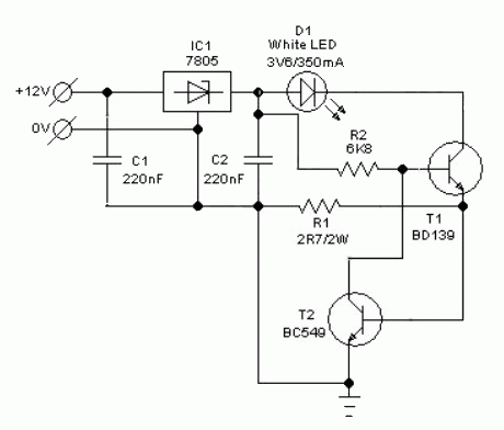
Without any dedicated buck converter/white crystal rectifier driver IC, you'll safely drive several customary Hi-efficient white crystal rectifier modules victimization the battery power out there in cars. Here may be a safe and easy white crystal rectifier driver designed for 12V cars.


Auto White LED Circuit Schematic


In the Automobile White crystal rectifier wiring, fastened transformer IC1 (7805) provides a gentle voltage of 5V across C2. Resistors R1 limits the present flow through the white crystal rectifier D1 (3v6/350mA) with the assistance of semiconductor T1 (and T2), i.e. parts R1, T1 (and T2) offer a relentless current to D1. Use a decent sink for T1. This crystal rectifier unit offers a relentless lightweight output for input voltages starting from eight to eighteen volts!

Outdoor Lighting Controller

When you step out of your brightly-lit house  into the darkness, it takes a while for your  vision to adjust. A solution to this problem  is this outdoor light with automatic switch-off. As a bonus, it will also make it a little bit  easier to find the keyhole when returning  late at night. Often no mains neutral connection is avail-able at the point where the switch-off timer  is to be installed, which makes many circuit  arrangements impractical. However, the circuit here is designed to work in this situation. The design eschews bulky components such as transformers and the whole unit can  be built into a flush-mounted fitting. The circuit also features low quiescent current consumption.

Outdoor Lighting Controller Circuit Diagram :

Outdoor Lighting Controller-Circuit Diagram
The circuit is star ted by closing switch (or  pushbutton) S1. The lamp then immediately receives power via the bridge rectifier. The drop across diodes D5 to D10 is 4.2 V, which provides the power supply for the delay circuit itself, built around the CD4060 binary  counter.

When the switch is opened the lighting sup-ply current continues to flow through Tri1. The NPN optocoupler in the triac drive circuit detects when the triac is active, with antiparallel LED D1 keeping the drive sym-metrical. The NPN phototransistor inside the  coupler creates a reset pulse via T1, driving  pin 12 of the counter. This means that the  full time period will run even if the circuit is retriggered. The CD4060 counts at the AC grid frequency.  Pin 3 goes high after 213clocks, which corresponds to about 2.5 minutes. If this is not long  enough, a further CD4060 counter can be cascaded. T2 then turns on and shorts the internal LED of opto-triac IC2; this causes Tri1 to  be deprived of its trigger current and the light  goes out. The circuit remains without power until next triggered.

The circuit is only suitable for use with resistive loads. With the components shown (in particular in the bridge rectifier and D5 to  D10) the maximum total power of the connected bulb(s) is 200 watts. As is well known, the filament of the bulb is most likely to fail at the moment power is applied. There is little risk to Tri1 at this point as it is bridged by  the switch. The most likely consequence of overload is that one of diodes D1 to D6 will  fail. In the prototype no fuse was used, as it would not in any case have been easy to change. However, that is not necessarily recommended practice!

Circuits at AC line potential should only be constructed by suitably experienced persons and all relevant safety precautions and  applicable regulations must be observed during construction and installation.
Author : Harald Schad - Copyright : Elektor

230 v Christmas Flash Light

This is Christmas season so you all may get ready to do lots of variations for your house for your gardens.In Christmas Christmas tree gets an important place so I decided to give very important circuit to decorate your Christmas tree here these bulbs are blinking.Moving 1M preset the speed of the bulb can be changed.about 20 bulbs (25w) Can be connected for this circuit.

 230 v Christmas Flash Light Circuit Diagram


Note

# All the resistors must be 1/4w.
# When you work with 230 be careful always try to get the assistance of an elder.

WHITE LINE FOLLOWER

This circuit will be used for a toy automotive to follow a white line. The motor is either a 3v sort with gearing to steer the automotive or a rotary actuator or a servo motor.When equal lightweight is detected by the photo 
resistors the voltage on the base of the primary transistor are mid rail and the circuit is adjusted via the 2k2 pot that the motor doesn't receive any voltage. When one in all the LDR's receives a lot of (or less) lightweight, the motor is activated. and also the same thing happens when the other LDR receives less or more light.


WHITE LINE FOLLOWER CIRCUIT DIAGRAM

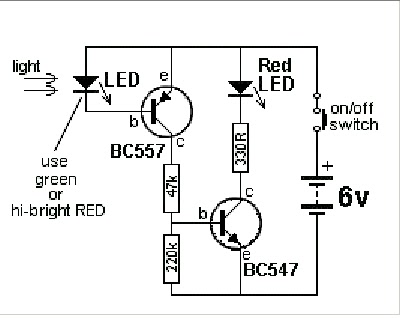
LED DETECTS lightweight

All LEDs offer off lightweight of a specific color however some LEDs also are able to detect lightweight. clearly they're not nearly as good as a tool that has been specially created to detect light; like solar cell, photocell, photo resistor, lightweight dependent resistor, photo transistor, photo diode and different photo sensitive devices.

A inexperienced LED can detect lightweight and a high-bright red LED can respond about a hundred times higher than a inexperienced LED, however the LED during this position in the circuit is classed as terribly high impedance and it needs a considerable quantity of amplification to show the detection into a worthwhile current-source. All different LEDs respond terribly poorly and aren't price making an attempt. The accompanying circuit amplifies the output of the LED and permits it to be used for variety of applications.
The LED solely responds when the sunshine enters the tip of the LED and this makes it ideal for solar rackers and any time there's an outsized difference between the dark and light-weight conditions. it'll not detect the


light in a very area unless the lamp is incredibly shut.

light in a very area unless the lamp is incredibly shut.

Portable Solar Lantern

This portable solar lantern circuit uses 6 volt/5 watt solar panels are now widely available. With the help of such a photo-voltaic panel we can construct an economical, simple but efficient and truly portable solar lantern unit. Next important component required is a high power (1watt) white LED module.

When solar panel is well exposed to sunlight, about 9 volt dc available from the panel can be used to recharge a 4.8 volt /600 mAh rated Ni-Cd batterypack. Here red LED (D2) functions as a charging process indicator with the help of resistor R1. Resistor R2 regulates the charging current flow to near 150mA.

Solar Lantern Circuit Schematic

Circuit Project: Portable Solar Lantern

Assuming a 4-5 hour sunlit day, the solar panel (150mA current set by the charge controller resistor R2) will pump about 600 – 750 mAh into the battery pack. When power switch S1 is turned on, dc supply from the Ni-Cd battery pack is extended to the white LED (D3). Resistor R3 determines the LED current. Capacitor C1 works as a buffer.

Note: After construction, slightly change the values of R1,R2 and R3 up/down by trial&error method, if necessary.

Cheap LED flashing circuit

This is an simple and cheap LED flashing circuit.This circuit work for at lease 10V-13V power supply.
Data sheet 2N2222 which is equivalent of KSP2222. 

Solar Powered Animal Scarer

Here is a solar powered Flasher to scare away the nocturnal animals like bats and cats from the farm yard or premises of the house. The brilliant multicolored flashes confuse these animals and they avoid the hostile situation. It is fully automatic, turns on in the evening and turns off in the morning.

The circuit has an LDR controlled oscillator built around the Binary counter IC CD 4060.The functioning of the IC is controlled through its reset pin 12. During day time, LDR conducts and keeps the reset pin of IC high so that it remains dormant. During night, LDR cease to conduct and the reset pin will be grounded through VR1. This triggers the IC and it stats oscillating using the components C1 and VR2. Output pins 7, 5 and 4 are used to power the LEDs strings.

VR1 adjusts the sensitivity of LDR and VR2, the flashing rate of LEDs. High bright Red, Blue and White LEDs are used in the circuit to give brilliant flashes. Red LEDs flash very fast, followed by blue and then White. White LEDs remains on for few seconds and provide light to a confined area. More LEDs can be added in the strings if desired. The circuit can also function with 12 volt DC.

Animal Repellent Circuit Diagram

Circuit Project: Solar Powered Animal Scarer

The circuit uses a solar powered battery power supply. During daytime, battery charges through R1 and D1.Green LED indicates the charging mode. During night time current from the solar cell decreases and D1 reverse biases. At the same time D2 forward biases to provide power to the circuit. Resistor R1 restricts the charging current and the high value capacitor C1 is a buffer for current.

Animal Scarer Solar Power Supply

Circuit Project: Solar Powered Animal Scarer

Simple Power LED Driver

If you want to operate power LEDS with a truly constant current which significantly prolongs the lifetime of the lamp and avoid the power loss resulting from using a constant voltage supply with a series resistor, you need a suit-able constant current source. However, the only way to achieve really good efficiency is to use a switching regulator. Altogether, this means that you need a switching regulator designed to generate a constant current instead of a constant voltage.

With this in mind, the author started working on the development of a LED pocket torch with especially high efficiency. Along with using high-capacity rechargeable batteries to maximise operating life, it’s worthwhile to be able to reduce the brightness, and therefore the operating current of the LEDs, when you don’t need full power. Accordingly, the author incorporated a dimming function in the design, based on operation in PWM mode in to reduce power losses to an absolute minimum.

Power LED Driver Circuit Diagram


Power LED Driver Circuit Diagram
As you can see from the circuit diagram, the author chose an LT3518 switching regulator IC, which is a buck/boost converter optimised for LED operation. Here it is used as a down converter (buck mode). This IC can achieve better than 90% efficiency in this mode, depending on the input voltage. According to the typical application circuit on the data sheet [1], its switching frequency can be set to approximately 170 kHz by selecting a value of 82 kΩ for R1. To maximise overall efficiency with this type of IC, the volt-age drop over the sense resistor used to measure the current flowing through the LED should be as low as possible. This particular device operates with a voltage drop of 100 mV, corresponding to a current of just under 1.5 A with the specified value of 68 mΩ for R2. This value proved to be suitable for the Cree LED used by the author. At this current level, a diode with a power rating of at least 6 W should be used for D1.

IC1 has an additional property that is ideal for this application: the connect-ed LED can be dimmed by applying a PWM signal to pin 7 of the IC, with the brightness depending on the duty cycle. Obviously, the PWM frequency must be lower than the switching frequency. The PWM signal is provided by IC2, a special voltage-controlled PWM generator (type LTC6992 [2]). The duty cycle is controlled by the volt-age applied to the MOD input on pin1 (range 0–1 V). The resistor connected to pin 3 determines the internal clock frequency of the IC according to the formula f= 1 MHz × (50 kΩ/R3). This yields a frequency of approximately 73.5 kHz with R3 set to 680 kΩ, which is much too high for controlling IC1.

However, the PWM IC has an internal frequency divider with a division factor controlled by the voltage applied to pin 4, which in this circuit is taken from voltage divider R4/R5. The division factor can be adjusted over the range of 1 to 16,384. The division factor with the specified component values is 64, resulting in a PWM frequency of around 1,150 Hz. If you want to be able to generate a PWM signal with an adjust-able duty cycle over the full range of 0 to 100%, you must use the LTC6992-1 option. The -4 option, which provides a range from 5 to 100%, might be an acceptable alternative.To prevent the duty cycle (and thus the brightness of the LED) from depending on the battery voltage, which gradually drops as the battery discharges, IC3 generates a stabilised 1.24 V control voltage for potentiometer P1. Series resistor R7 reduces the voltage over P1 to 1V, which exactly matches the input voltage range of the LTC6992.

All capacitors should preferably be ceramic types, in particular due to their low effective series resistance (ESR) as well as other favourable characteristics. However, only capacitors with X5R or X7R dielectric should be used; capacitors with type Y dielectric have very poor temperature characteristics.The supply voltage is limited to 5.5V by the maximum rated supply voltage of IC2. The author used four NiMH re-chargeable cells connected in series, which yields a voltage that is just within spec. With an operating voltage in the range of 4.5 V to 5.5 V, you must use an LED that can operate at less than 4V.

This eliminates devices with several chips connected in series on a carrier, which is very often the case with power LEDS rated at over 5 W. These devices require a correspondingly higher supply voltage, which means more cells connected in series. This is only possible if the supply voltage for IC2 is reduced by a 5 V voltage regulator or other means, and of course R4 must also be connected to this lower supply voltage.

Finally, a few words about soldering. An exposed thermal pad must be provided on the PCB for the LT3518, and the rear face of the IC must be soldered to this pad. The author obtained good results by dimensioning the exposed pad large enough to extend beyond the outline of the IC. When assembling the board, first tin the pad and the rear face of the IC. Then heat the pad with a soldering iron. When the solder melts, withdraw the tip of the soldering iron to the edge of the pad and simultaneously place the IC on the pad and align it. After this the pins can be soldered.

Author : Burkhard Kainka Copyright: Elektor

2-Pin Automobile Indicator Lamp Flasher Circuit with Buzzer

If you want to make a flasher unit for you motorbike then this circuit is just for you. This simple turn signal flasher circuit can be  easily built and installed in any two wheelers for the desired actions. The circuit employs just two 2-pins instead of 3 as found in other flasher circuits. Once installed, the circuit will faithfully flash the side indicator lights whenever the intended function is switched ON. The circuit also incorporates an optional buzzer circuit which can be also included for getting a beeping sound in response to the flashing of the lamps.


.
Parts List
R1, R2, R3 = 10K
R4= 33K
T1 = D1351,
T2 = BC547,
T3 = BC557,
C1, C2 = 33uF.25V
L1 = Buzzer Coil

The Portable Solar Lantern

This portable solar lantern circuit uses 6 volt/5 watt solar panels are now widely available. With the help of such a photo-voltaic panel we can construct an economical, simple but efficient and truly portable solar lantern unit. Next important component required is a high power (1watt) white LED module.

When solar panel is well exposed to sunlight, about 9 volt dc available from the panel can be used to recharge a 4.8 volt /600 mAh rated Ni-Cd batterypack. Here red LED (D2) functions as a charging process indicator with the help of resistor R1. Resistor R2 regulates the charging current flow to near 150mA.

Solar Lantern Circuit Schematic

Circuit Project: Portable Solar Lantern

Assuming a 4-5 hour sunlit day, the solar panel (150mA current set by the charge controller resistor R2) will pump about 600 – 750 mAh into the battery pack. When power switch S1 is turned on, dc supply from the Ni-Cd battery pack is extended to the white LED (D3). Resistor R3 determines the LED current. Capacitor C1 works as a buffer.

Note: After construction, slightly change the values of R1,R2 and R3 up/down by trial&error method, if necessary.

Flash Relay

Hello! in this post I will show a very small circuit, the relay opens and closes its contacts intermittently, the speed can be changed by changing the value of C1, the output relay can be turned on an LED, working as a wink - wink! The relay coil and the capacitor voltage is in accordance with the circuit power! 

See the figure below:


New Dark Activated Terrace Lamp

Compact circuit, Can be wired in parallel to existing switches This device allows one or more lamps to illuminate at sunset and turn off at dawn.Q1 and Q2 form a trigger device for the SCR, providing short pulses at 100Hz frequency. Pulse duration is set by R2 and C1.When the light hits R1, the photo resistor assumes a very low resistance value, almost shorting C1 and preventing circuit operation. When R1 is in the dark, its resistance value becomes very high thus enabling circuit operation.

 Circuit Diagram:

http://diagramdigital.blogspot.com/2012/09/new-dark-activated-terrace-lamp.htmlDark Activated 220 volt AC Lamp Circuit Diagram

Parts:


R1 = LDR
R2 = 100K
R3 = 200K
R4 = 470R
R5 = 12KR6 = 1KR7 = 470R
C1 = 10nF-63V
D1 = TIC106D
D2 = 1N4007D3 = 1N4007D4 = 1N4007
D5 = 1N4007
Q1 = BD327
Q2 = BD337
SK1 = Female Mains Socket
 
Notes:

  • R3 allows fine setting of operating threshold and R2 value can be raised to 150K maximum.
  • Several lamps wired in parallel can be connected to the circuit, provided total power dissipation of the load does not exceed about 300 - 500W.
  • PL1 can be omitted and the input mains supply wires connected in parallel to any switch controlling lamps. In this case, if the switch is left open, the circuit will be able to drive the lamps; if the switch is closed, the lamps will illuminate and the circuit will be by-passed.
  • Warning! The circuit is connected to 230Vac mains, and then some parts in the circuit board are subjected to lethal potential! Avoid touching the circuit when plugged and enclose it in a plastic box.


Source: Red Free Circuit Design

Simple Cmos Universal Logic Probe Circuit Diagram

Simple Cmos Universal Logic Probe Circuit Diagram. Only the CD4009AE hex buffer, two resistors, and two LEDs are required for a logic probe. CMOS logic probe features 10120 input impedance and covers 3 to 15 V range. While LEDs are visible at all voltages, a 1-K!l pot in place of R2 will allow the user to increase brightness at lower voltages. 

Simple Cmos Universal Logic Probe Circuit Diagram


Simple Cmos Universal Logic Probe Circuit Diagram

Older Post ►
eXTReMe Tracker
 

Copyright 2011 Diagram Digital Schematic is proudly powered by blogger.com