Showing posts with label Preamplifier and Tone. Show all posts

Vocal Adaptor for Bass Guitar Amp

These days, music is a major hobby for the young and not-so-young. Lots of people enjoy making music, and more and  more dream of showing off their talents on  stage. But one of the major problems often encountered is the cost of musical equipment. How many amateur music groups sing through an amp borrowed from a guitarist or bass player? 

This is where the technical problems arise not in terms of the .25” (6.3 mm)  jack, but in terms of the sound quality (the words are barely understandable) and volume (the amp seems to produce fewer decibels than for a guitar). What’s more, unpredictable feedback may cause damage to the speakers and is very unpleasant on the ear. This cheap little easy-to-build project can help solve these technical problems.

Vocal Adaptor for Bass Guitar Amp-Circuit Diagram


A guitar (or bass guitar) amplifier is designed first and foremost to reproduce the sound of the guitar or bass as faithfully as possible. The frequency response of the amp doesn’t need to be as wide or as flat as in hi-fi (particularly at the  high end), and so this sort of amplifier won’t  permit faithful reproduction of the voice. If you build an adaptor to compensate for the amp’s limited frequency response by amplifying in advance the frequencies that are then attenuated by the amp, it’s possible to improve the quality of the vocal sound. That’s just what this circuit attempts to do. 

The adaptor is built around the TL072CN low-noise dual FET op-amp, which offers good value for money. The NE5532 can be used with almost the same sound quality, but at (slightly) higher cost. The circuit breaks  down into two stages. The first stage is used to match the input impedance and amplify the microphone signal. For a small 15 W guitar or bass amplifier, the achievable gain is about 100 (gain = P1/R1). For more 

powerful amplifiers, the gain can be reduced to  around 50 by adjusting P1. The second stage  amplifies the band of frequencies (adjustable using  P2 and P3) that are attenuated by the guitar amp, so as to be able to reproduce the (lead) singer ’s voice as clearly, distinctly, and  accurately as possible. To refine the adaptor and tailor it to your amplifier and speaker, don’t be afraid to  experiment with the component values and the type of capacitors. 

The circuit can readily be powered using a 9 V battery, thanks to the voltage  divider R4/R5 which converts it into a symmetrical  ±4.5 V supply.


Author :Jérémie Hinterreiter
Simple Accurate Bass Tone Control

A difficult problem in the design of conventional stereo tone controls is obtaining synchronous travel of the potentiometers. Even a slight error in synchrony can cause phase and amplitude differences between the two channels. Moreover, linear potentiometers are often used in such controls, and these give rise to unequal performance by human hearing. Special potentiometers that counter these difficulties are normally hard to obtain in retail shops. A good alternative is a control based on a rotary switch and a discrete potential divider. The problem with this that for good tone control more than six steps are needed, and switches for this are also not readily available. Fortunately, electronic circuits can remove these difficulties.

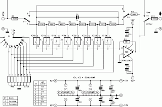
 Simple Accurate Bass Tone Control Circuit Diagram

The analogue selectors used may be driven by mechanical switches, standard logic circuit or a microcontroller. The selectors used in the present circuit are Type SSM2404 versions from Analogue Devices, which switch noiselessly. Each IC contains four selectors, so that a total of eight are used. The step size is 1.25 dB at 20 Hz with a maximum of 10dB . The circuit can be mirrored with S1, which means that a selection may be made of amplification or attenuation of bass frequencies. The user can choose between attenuation only and extending the range by dividing R9. The control can be bridged by switch S2.

To prevent the output impedance of the circuit having too much effect on the operation of the circuit, the output impedance must be ≤ 10 Ω. Resistor R1 2 protects the circuit against too small a load. At maximum bass amplification at Ui n = 1 V r.m.s., the THD+N <0.001% for a frequency range of 20 Hz to 20kHz and and a bandwidth of 80kHz. The circuit draws a current of about 10 mA.

Simple Phono Preamplifier Circuit Diagram

This is a Simple Phono Preamplifier Circuit Diagram. In recent years, following CD's introduction, vinyl recordings are almost disappeared. Nevertheless, a phono preamplifier is still useful for listening old vinyl discs from a well preserved collection. This simple but efficient circuit devised for cheap moving-magnet cartridges, can be used in connection with the audio power amplifiers shown in these web pages, featuring low noise, good RIAA frequency response curve, low distortion and good high frequency transients behavior due to passive equalization in the 1 to 20 KHz range.
Simple Phono Preamplifier Circuit Diagram


Parts:

R1 = 47K
R2 = 100R
R2 = 6.8K
R4 = 68K
R5 = 2.7K-1/2W
R6 = 2.7K-1/2W
R7 = 2.2K
R8 = 39K
C1 = 100uF-25V
C2 = 100uF-25V
C3 = 100uF-25V
C4 = 47nF-63V
C5 = 47nF-63V
D1 = BZX79C18
D2 = BZX79C18
Q1 = BC337
Q2 = BC327
J1 = RCA Jack
IC1 = LM833, Opamp

Notes:
  • R2, R3, R4, R7, R8, C4 & C5 should be low tolerance types.
  • Schematic shows left channel and power supply.
  • For stereo operation R1, R2, R3, R4, R7, R8; J1; C1, C4 & C5 must be doubled.
  • Numbers in parentheses show IC1 right channe
Older Post ►
eXTReMe Tracker
 

Copyright 2011 Diagram Digital Schematic is proudly powered by blogger.com